Inventor Sheet Metal Flange Offset
Inventor Sheet Metal Flange Offset Autodesk Community

Solved Sheet Metal Flange Only On Partial Edge Autodesk Community Inventor

Inventor Sheet Metal Flange Bend Edit Offset Autodesk Community
How To Move An Inventor Sheet Metal Flange Along Edge Or Certain Length On Edge Inventor 2018 Autodesk Knowledge Network

Solved Sheet Metal With Partial Fold Autodesk Community Inventor

Solved Sheetmetal Flange Mitre Problem Autodesk Community Inventor

Create a 2d open profile sketch.
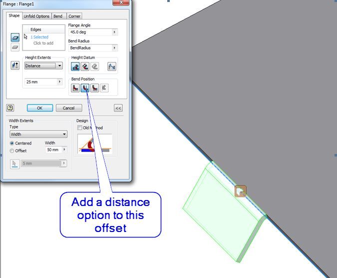
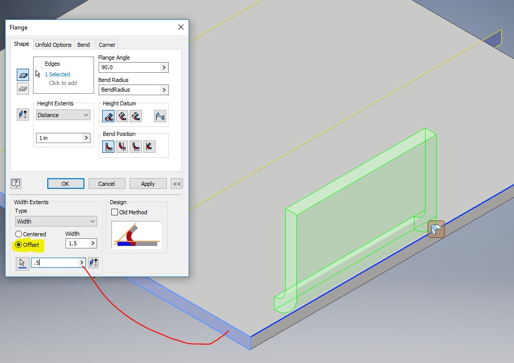
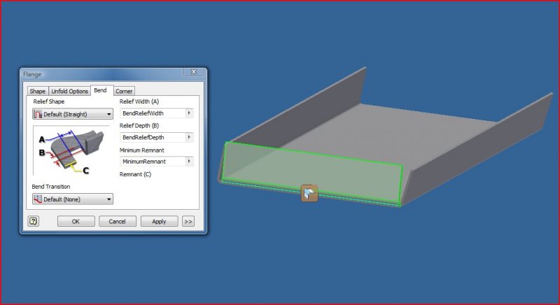
Inventor sheet metal flange offset.
Sheet Metal Angled Flange Problem Autodesk Inventor Autocad Forums

Solved Sheet Metal Flanges On Angles Autodesk Community Inventor

Overdue Improvements To Inventor Sheet Metal Autodesk Community

Solved The Extents Feature Is Grey Out In Contour Flange Of Sheet Metal Autodesk Community Inventor
Source : pinterest.com
